During my journey to perform an RGB mod to a TV
for my arcade machine [here],
I found that I had to add multiple features to
make it work, and so I converted the breadboard
design into a customized PCB that will handle most
needs for RGB modders for both console and arcade
users.
Is this board really necessary? Not really as much
of the work can be covered by a few wires and
components to an existing TV. As a result, for
simpler mods, I would not necessarily recommend
this board, although you could consider using the
"mini" version of this universal board for simpler
console + TV applications (see below for a sample
installation).
For more complex mods that might require managing
the sync signal, adding an auto-start feature, or
to have the ability to adjust color levels, then
this board may be useful and a time saver,
particularly for arcade users.
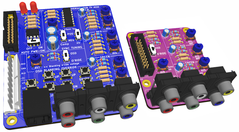
Here are early renders of the full standard board
and mini board.
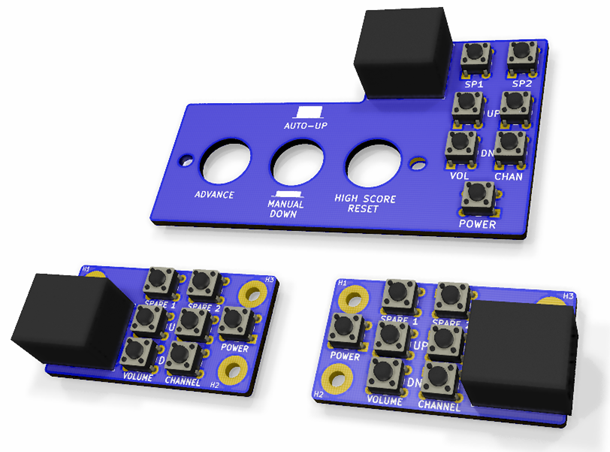
For the arcade users, here are additional renders
of various remote buttons that can be installed in
the coin door for the Williams arcade machines
(top) as well as left-handed and right-handed
generic remotes.
The design goals for this universal RGB board are:
|
Feature
|
Standard
Board
|
Mini
Board
|
|
Compatible with MarkOZLAD's basic mux
circuit
-
Support for 75 ohm termination
resistors if needed
-
Support for diodes and capacitors
if needed
-
Adjustable OSD blanking signal
(1-5V) as some TVs require 3.3V
for analog RGB
-
Mux resistors to set the RGB gain,
made adjustable by using pots if
desired
|
Yes
|
Yes
|
|
Easy to
customize
-
Some soldering is required, but no
surface mount components are used,
and pads are relatively large to
aid in soldering.
|
Yes
|
Yes
|
|
RCA
jack inputs for Red, Green, Blue (RGB)
and Negative Composite Sync input
-
Using RCA jacks are optional -
user does not need to install the
RCA jacks
-
Alternatively, user can solder
pins or can solder the external
inputs directly into the board, or
can have remote RCA or BNC jacks.
|
Yes
|
Yes
|
|
Compatible for console/SCART users
-
See
Section 3 below for details.
|
Yes
|
Yes
|
|
Full
support for integrating TVs into
arcade machines - i.e. anything
with a 240p 15kHz signal
-
Compatible with 7 and 10 pin
arcade video plugs of CRT monitors
-
*Partial for the mini-board: with
an adapter cable, the arcade
output can be plugged into the
mini board, and as long as the
arcade machine puts out a negative
composite sync, then it should
work. For example: Williams arcade
machines can be hacked to output
the proper sync signal
[here].
|
Yes
|
Partial*
|
|
Compatible with VGA output from
devices such as a Raspberry Pi or a PC
*
Mini-board requires a compatible
(negative) C Sync output. see Section
4 below for details.
|
Yes
|
Partial*
|
|
Compatible with the JROK arcade boards
- see
Section 5 for details.
|
Yes
|
Partial*
|
|
Compatible with 31kHz output and/or
higher resolution
*
Requires a downscaler to convert 31kHz
to 15kHz.
|
Partial*
|
Partial*
|
|
Compatible with the Sanyo Jungle Chip
LA76843N or similar
-
Example are Sharp TVs such as TV
Model 19C140, 19R-M100 ,19N-M100,
20N-S100S, 25R-S100, etc.
-
These are also identified as
Jungle Chip IC201 IX3354CE
-
Often also equipped with the OSD
chip: IC2001 IX3492CE
-
Note: The jungle chip in these TVs
typically work as a digital input
at full brightness but also have
an alternate limited RGB input
voltage range that require a DC
offset feature.
|
Yes
|
No
|
|
Combine
Horizontal, Vertical Sync into a
Composite Sync signal
-
Mini-board can only accept
negative composite sync
|
Yes
|
No
|
|
Convert
positive Sync (HV or composite) into a
negative Sync
|
Yes
|
No
|
|
Automatic power-on feature to turn on
the TV when plugged in for arcade
machines
-
There is
a switch allows this
feature to be turned on or off as
required
-
Two LEDs show the status of the
two power circuits
|
Yes
|
No
|
|
Remote
mounted TV switches for arcade
machines
-
Allows TV switches to be
accessible via the coin door
-
Two designs are available: generic
or optimized for Williams arcade
machines
-
Not required for console users
|
Yes
|
No*
|
SECTION 1 - How to obtain this board
All design files, drawings, etc. to have your own
board manufactured are located
[here].
** COMING MARCH 2022 **
As a one-time opportunity, I ordered a few spares
so you can purchase this board with or without
components
[here] **
COMING MARCH 2022 **. If it is no longer
available, you can still download the files, and
then upload the manufacturing zip file (included
in the download) to the PCB manufacturer of your
choice.
Note: because there are many choices to be made
such as resistor values, diodes (yes or no),
capacitors (yes or no), positive or negative sync,
this board is not available with the components
pre-populated. Therefore this is for people who
are comfortable with soldering. To make things
easier, there are
no surface mounted components, and the
soldering pads are relatively large to ease
soldering.
SECTION 2 - Assembly Instructions
The zip file download includes instructions to
decide which components to install, which ones to
skip, and which ones to bypass, and how/where to
install the board. You can also view these
instructions [here].
** COMING MARCH
2022 **
SECTION 3 - General thoughts on SCART and VGA
inputs
If you are looking at a SCART option to use with
this universal board design, look for space to
mount the board inside the TV and connect the RGBC
ports of the board to remote RCA or BNC jacks or
to a SCART plug on the TV back panel.
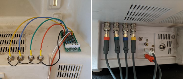
An example of remote ports on a TV is shown
[here].
Note: these pics are not of my board, but installation would be similar.
Afterwards, you should be able to use a standard
SCART-to-RCA (or BNC) cable adapter.
Important:
I have not tested this scenario, and I currently
do not plan to.
Board shown in
picture is not this universal board, but concept
is identical
-
Optional SCART 15 kHz support through a
SCART-to-RCA RGBS cable adapter, with the "S"
(Sync) output being the Composite Sync (not tested, so proceed at your own
risk).
Note, you might be better served to build your
own, but this adapter on ebay seems to be the
correct one [here]
-
Optional VGA 15 kHz support through a
VGA-to-RCA RGBHV cable adapter (tested and it
worked)
-
ebay - option #1 with male RCA jacks [here]
- hard to find anywhere. This is the last
one on ebay.
-
ebay - option #2 with female RCA jacks [here]
- easier to find, but need adapters [here]
-
ebay - option #3 with BNC jacks [here]
and comes with proper adapters
-
Ebay - option #4 with BNC jacks [here]
- easy to find, and you can select a cable
length that makes sense for your
installation, but need adapters like these
[here]
-
Optional VGA 15 kHz support through an
[Extron
192 on ebay]
adapter (tested and works, but I had some
light noise on the display which might have
been from the cables I used)
-
Optional VGA 31 kHz support through a [GBS-8200
Open Source Mod]
downscaler (not tested, but I plan to test
this eventually)
SECTION 4 - Thoughts on using a Raspberry Pi or a
PC
Note:
-
Tested with a Raspberry Pi3B+ with Retroarch
using an older Lakka v232 download
-
Not tested using a PC, but there is plenty of
material on putting out 240p via older ATI
graphics cards
-
Equipment used
-
Rasberry Pi 3B+ with a good power supply
-
an HDMI-to-VGA adapter (whatever was
available on Amazon)
-
Lakka's official Retroarch distro for the
Raspberry Pi
-
I used an older Lakka v232, but newer
versions should work as well or better
-
Setting the Raspberry Pi output to 240p
-
I followed the instructions given in
this post [here]
-
I had to do multiple tweaks (which are
above and beyond the intent of this
post), but I posted my process on this
forum, but the key discovery is that
my widescreen Dell monitor U3415W
works at 15kHz, so I was able to test
all the settings at my desk.
-
Alternatively, you can use a device to
convert the 31kHz VGA output to 15kHz
downscaler such as a
GBS8200/8220 (see link above)
-
Here are the results of the Raspberry Pi test
(see the post [here]
for pictures):
-
It worked fine with no issues with the
prototype board.
-
Tested with VGA output through an Extron
192 to combine HV into a negative C Sync
-
The Extron is needed if using the
"mini" board because it is missing the
HV to Composite combiner circuit.
-
Had some very light noise in the image
- possibly due to bad cables?
-
Also tested with a direct VGA-to-RGBHV
cable straight into the board, and the
results were outstanding with zero noise
whatsoever.
SECTION 5 - Thoughts on using a JROK arcade board
You have two options for using the JROK board with
a TV CRT and the standard universal adapter board:
-
Option 1: Use the arcade
output 7 pin MOLEX to the universal's board
7/10 pin MOLEX (or make an adapter cable to
plug into the RCA jacks)
-
Recommended as it
is a far simpler installation
-
This is what I tested, and it worked great
-
Option 2: Use the VGA output
of the JROK at 31 kHz, run it through a
downscale converter to bring the signal down
to 15 kHz, and then into the universal board,
either through the RCA plugs or through the
MOLEX connector
-
Not tested.
-
There are multiple 31 to 15 kHz converters
out there, and I will not test those
except for the [GBS-8200
Open Source Mod]
which I will test when I get mine,
and modify it accordingly.
And finally, I also realize that there
was another attempt at a similar board that
also used an amplifier for muxing [here].
That board utilized surface-mounted components,
and is another smaller solution that can be
considered for your application.